Where the energy from solar panels is not enough, it is essential to have an all-weather power source to recharge the batteries of a home solar power system.
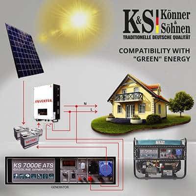
Generators of TM “Könner & Söhnen” with a built-in ATS system (Automatic Transfer Switch) are powerful enough to charge the batteries of the majority of mini solar power systems and can be turned on and off if necessary.
This guide offers our solutions that can be applied not only in most home solar power systems, but also in other storage battery systems, although with slight adjustments.
In this case, the generator’s purpose is solely to charge the battery. Consumers are supplied with “pure sine” voltage from the inverter.
The generator start/stop is controlled either by the battery voltage control unit contacts or by the programmable “dry contacts” of the inverter. These contacts must withstand a voltage of 250 V and a current of up to 1 A. The output voltage of the inverter is fed through these contacts to the generator ATS unit and is used to power the ATS unit as well and to charge the generator battery. The generator is started or stopped through interruption or resumption of the external power supply to the ATS unit.
It is recommended that an external charger with integrated power factor correction (PFC) be used to charge the storage battery. It is further recommended that a compensating load (for example, an incandescent lamp bulb) be used to absorb the energy of voltage pulses arising from the non-linear charger consumption at power factors less than 0.95.
Charging modules used in inverters typically have a power factor of 0.5-0.7 and can cause significant distortion in the generator output voltage due to the fact that they take energy from only part of the sine wave, which can damage the generator. The compensating linear load provides the load of the unloaded sections of the sine wave and damping of voltage impulses harmful to the generator. In addition, the built-in charging modules are generally low power and are designed to slowly charge the battery.
The “bypass” function must be disabled should the storage battery be charged by the built-in inverter module. If this is not possible, then it is recommended to use the KS 8100iE ATSR inverter generator with an external KS ATS 4/25 Gasoline ATS-unit, since its output voltage is less prone to distortion than that of conventional generators and can be switched direct to power consumers.
The automatic transfer switch used ensures that voltage is supplied to the charger only after the generator has started. A generator start test can be performed by interrupting the circuit with circuit breaker 2 without tripping the automatic transfer switch as long as the voltage is applied to its N side. The entire function of the system, including the charger operation, can be tested by interrupting the circuit with circuit breaker 1.
Below is the recommended connection layout with the use of an external charger and an external storage battery voltage control unit:

Below is the recommended connection layout with the use of an external charger and programmable “dry contacts” (250 V, 1 A) of the inverter:

Below is the recommended connection layout with the use of a built-in inverter charger (“bypass” function is disabled) and an external storage battery voltage control unit:

Below is the recommended connection layout with the use of a built-in inverter charger (“bypass” function is disabled) and programmable “dry contacts” (250 V, 1 A):

Our generators are supplied as an IT system and the neutral is nit connected to the generator frame. The PE contact in sockets is connected to the generator frame, and the L and N current-carrying wires are isolated. The generator neutral is grounded at the output of the automatic transfer switch (TN system).
Please note!
Disclaimer:
This guide and connection layouts should be viewed solely as a recommendation and, if necessary, be adapted to the actual operating conditions, taking into account all the regulations and standards for the given area. We, as a generator manufacturer, assume no liability for incorrect installation, operation and/or any consequences thereof.